
Honeywell Pro 8000 Installation Manual: A Comprehensive Guide
This manual details the Honeywell Pro 8000 system’s installation, operation, and maintenance, offering essential guidance for users beginning their journey with this security solution.
The Honeywell Pro 8000 is a sophisticated security system designed to provide comprehensive protection for residential and small commercial properties. This system integrates a robust control panel with a variety of wireless and wired sensors, offering customizable security solutions tailored to individual needs.
Featuring advanced encryption and communication protocols, the Pro 8000 ensures secure and reliable operation. Its user-friendly interface, coupled with mobile app connectivity, allows for remote control and monitoring of the system. This introduction will guide you through the core components and functionalities of the Honeywell Pro 8000, preparing you for a successful installation and ongoing operation. Understanding these basics is crucial for maximizing the system’s potential and ensuring your peace of mind.

Package Contents & Initial Inspection
Upon receiving your Honeywell Pro 8000 system, carefully inspect the package for any signs of damage during shipping. Verify that all listed components are present before proceeding with installation. The standard package typically includes the control panel, a keypad, several door/window sensors, a motion detector, a siren, and necessary mounting hardware.
A detailed packing list is included within the box; compare the contents against this list to ensure completeness. Report any missing or damaged items to your retailer immediately. Retain all original packaging materials for potential returns or warranty claims. Thorough initial inspection prevents delays and ensures a smooth installation process.
System Requirements & Compatibility
The Honeywell Pro 8000 system requires a standard 120V AC power supply with battery backup for uninterrupted operation. Ensure a dedicated electrical outlet is readily accessible near the intended control panel location. Compatibility extends to various communication protocols, including Wi-Fi for mobile app connectivity and cellular options for backup communication.

This system supports a wide range of Honeywell sensors and accessories, but compatibility with third-party devices may be limited. Verify sensor compatibility before installation. A stable internet connection is crucial for remote access and firmware updates. Confirm your home network meets the system’s minimum bandwidth requirements for optimal performance.
Safety Precautions & Warnings
Prior to installation, disconnect power to the circuit where the control panel will be installed to avoid electrical shock. Always wear appropriate safety glasses and gloves during wiring and handling of components. Do not attempt to disassemble or repair any internal components – refer servicing to qualified technicians.
Keep small parts and packaging materials away from children. Ensure proper grounding of the system to prevent static discharge damage. Avoid installing the control panel in areas exposed to extreme temperatures or moisture. Regularly test the system’s battery backup to ensure continued operation during power outages. Failure to follow these precautions could result in injury or system malfunction.
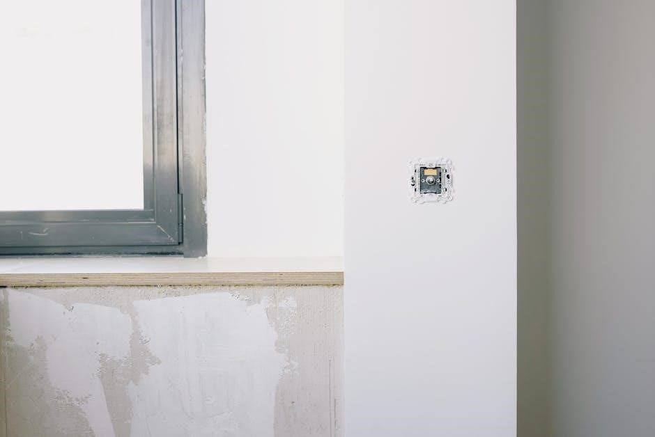
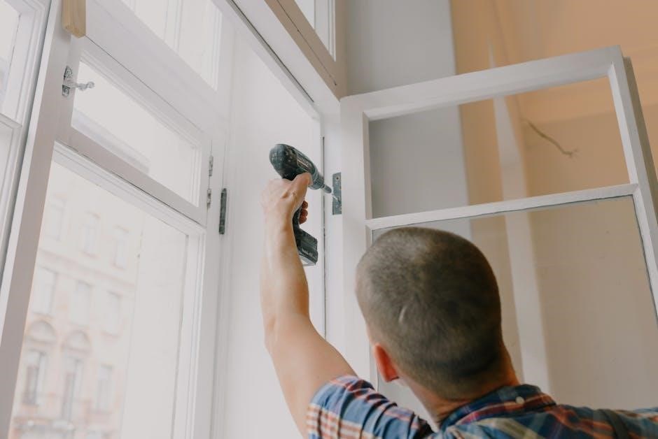
Control Panel Installation
Begin by selecting a secure, central location for the control panel, ensuring easy access for maintenance and wiring. Mount the backplate firmly to the wall using the provided screws, verifying it is level. Carefully connect the wiring harness, referencing the detailed wiring diagram for correct terminal assignments.
Connect the power supply, ensuring correct polarity. Before fully securing the panel, double-check all wiring connections for tightness and accuracy. Activate the system and verify the panel powers on correctly. Finally, secure the control panel to the backplate, ensuring all connections remain intact.
Mounting Location Considerations
Selecting the ideal mounting location is crucial for optimal system performance. Choose a central indoor location, minimizing the distance to all sensors. Avoid areas prone to extreme temperatures, humidity, or direct sunlight. Ensure the location provides easy access for future maintenance and troubleshooting.
Consider proximity to a power outlet for the system’s power supply. The mounting surface must be structurally sound and capable of supporting the panel’s weight. Avoid mounting near large metal objects that could interfere with wireless communication. Prioritize a discreet location, minimizing visibility to potential intruders, while maintaining accessibility for authorized users.
Wiring Diagram Overview
The Honeywell Pro 8000 utilizes a standardized wiring scheme for seamless integration of various security components. Refer to the detailed wiring diagram included in this manual for precise connection points. Key connections include power supply (12VDC), communication bus (4-wire), and sensor inputs (typically NO/NC).
Pay close attention to polarity when connecting the power supply to avoid damaging the control panel. Properly identify and label all wires before making connections. The diagram illustrates the wiring for keypads, door/window sensors, motion detectors, and sirens. Ensure all connections are secure and comply with local electrical codes.
Backplate Installation & Connections
Begin by securely mounting the backplate to the chosen wall using the provided screws and anchors, ensuring it’s level. Route the necessary wiring through the designated openings in the backplate before fully tightening. Connect the wiring harness to the terminal blocks, matching wire colors to the labeled designations – power, ground, communication bus, and auxiliary connections.
Double-check all connections for tightness and correct placement before proceeding. Ensure no bare wires are exposed to prevent short circuits. The backplate provides a stable foundation for the control panel and facilitates easy access for future maintenance or upgrades.
Keypad Installation & Configuration
The Honeywell Pro 8000 keypad offers multiple mounting options for convenient access and control. Choose a location near an entry/exit point, ensuring it’s within reach and visible. Connect the keypad wiring to the control panel, typically using a four-wire connection for power and communication.
During initial configuration, the system will prompt you to enroll the keypad. Follow the on-screen instructions to assign a unique device ID and communication settings. Basic programming includes setting the date, time, and language preferences. Test the keypad functionality to confirm proper operation before proceeding.
Keypad Mounting Options
The Honeywell Pro 8000 keypad provides versatile mounting solutions to suit various installation environments. Surface mounting is the most common method, utilizing screws and anchors for secure attachment to a wall. Recessed mounting offers a cleaner aesthetic, requiring a cutout in the wall to accommodate the keypad’s housing.
Consider the keypad’s proximity to power sources and communication wiring when selecting a location. Ensure the mounting surface is stable and capable of supporting the keypad’s weight. Avoid areas exposed to extreme temperatures or moisture. Utilize the included mounting template for precise hole placement and alignment.
Keypad Wiring & Communication
Proper keypad wiring is crucial for reliable communication with the Honeywell Pro 8000 control panel. Typically, keypads connect via a four-wire system – power, ground, data, and auxiliary. Refer to the wiring diagram for specific terminal assignments. Ensure all connections are secure and properly insulated to prevent shorts or interference.
The communication protocol utilizes a dedicated communication bus, allowing for bi-directional data exchange. Verify the wire gauge meets the system’s requirements to minimize voltage drop. Polarity must be observed for power and ground connections. Incorrect wiring can lead to keypad malfunction or system instability.
Keypad Programming Basics
Initial keypad programming involves assigning a unique ID to each keypad, ensuring the control panel recognizes it. Access the programming mode through the master code and navigate the menu using the keypad buttons. Common settings include date/time configuration, entry/exit delay adjustments, and chime volume control.
User codes are programmed directly through the keypad interface, granting authorized access to the system. Remember to document all user codes securely. Advanced programming options allow customization of features like duress codes and alarm verification settings. Consult the full programming guide for a comprehensive list of available options and their functionalities.
Sensor Installation (Doors & Windows)
Proper sensor placement is crucial for reliable security. Install door and window sensors on both the frame and the moving part, ensuring alignment when closed. Supported sensor types include recessed magnetic contacts and surface-mounted options. Wireless sensors require pairing with the control panel using the designated enrollment process.
Wired sensor installation necessitates running low-voltage wiring from the sensor to the control panel. Always test the sensor functionality after installation, verifying proper communication with the system. Consider using tamper protection features to detect unauthorized removal or interference. Refer to the wiring diagrams for correct connections.
Types of Sensors Supported
The Honeywell Pro 8000 system boasts compatibility with a diverse range of sensors, enhancing its adaptability. Supported wireless sensors include door/window contacts, motion detectors, and glass break detectors, utilizing secure encrypted communication. Wired sensors, such as magnetic contacts and foil sensors, offer a reliable alternative, connecting directly to the control panel.
Furthermore, the system supports specialized sensors like smoke detectors, carbon monoxide detectors, and flood sensors, expanding its protective capabilities. Ensure all sensors are listed as compatible within the Honeywell ecosystem for optimal performance. Refer to the compatibility list for specific model numbers and features.
Wireless Sensor Pairing Process
To pair a wireless sensor with your Honeywell Pro 8000 system, first, enter the panel’s programming mode using your master code. Navigate to the sensor pairing section within the programming menu – typically labeled “Add Device” or similar. Next, activate the sensor’s tamper switch, often by removing its battery cover or pressing a dedicated button.
The control panel should then initiate a search for the new sensor. Once detected, the sensor will appear on the screen with a unique identifier. Assign a descriptive zone name and type to the sensor. Confirm the pairing, and test the sensor’s functionality to ensure proper communication.
Wired Sensor Installation Guidelines
When installing wired sensors, always begin by disconnecting power to the control panel. Run the sensor wiring through appropriate conduit, adhering to local electrical codes. Ensure wires are properly labeled for easy identification during troubleshooting. Connect the sensor wires to the designated terminals on the control panel’s circuit board, matching polarity correctly.
Securely mount the sensor in its desired location, ensuring it’s aligned and functioning as intended. Double-check all connections for tightness and insulation. Restore power to the panel and test the sensor’s operation through the system’s programming menu. Proper wiring is crucial for reliable alarm system performance.
Motion Detector Installation & Testing
Carefully select the motion detector’s location, avoiding direct sunlight, heat sources, and areas with high air flow. Mount the detector securely at the recommended height, ensuring its field of view covers the intended area. Connect the wiring to the control panel, following the wiring diagram.
After installation, power on the system and enter test mode. Walk through the detection area to verify the sensor triggers an alarm. Adjust the sensitivity settings as needed to minimize false alarms. Regular testing is vital to confirm continued functionality and reliable protection. Proper placement and sensitivity calibration are key.
Siren & Alarm Device Installation
Choose a strategic location for the siren, ensuring it’s audible throughout the protected premises, but shielded from direct weather exposure. Mount the siren securely to a solid surface, utilizing appropriate hardware. Connect the wiring to the control panel, strictly adhering to the provided wiring diagram.
Verify proper polarity before powering on the system. Test the siren functionality during system testing, confirming a loud and clear alarm signal. Consider installing multiple sirens for larger properties. Ensure compliance with local regulations regarding alarm sound levels. Regularly inspect wiring and mounting for security.
System Programming & User Codes
Access the system programming mode via the keypad, typically requiring a master code. Navigate the menu options to configure system settings, including entry/exit delays and alarm responses. Create unique user codes for each authorized individual, assigning appropriate access levels.
Avoid easily guessable codes like birthdays or addresses. Document all user codes securely, separate from the system. Regularly update or change codes for enhanced security. Utilize the system’s features for temporary or one-time access codes. Review programming settings periodically to ensure they align with security needs.

Network Connectivity & Mobile App Setup
Connect the Honeywell Pro 8000 control panel to your home network via Ethernet or Wi-Fi. Ensure a stable internet connection for remote access and features. Download the Honeywell Home mobile app from your device’s app store. Create an account or log in if you already have one.
Follow the in-app instructions to pair your system, typically scanning a QR code or entering the panel’s serial number. Configure push notifications for instant alerts. Explore remote control features, such as arming/disarming and viewing system status. Regularly check for app updates for optimal performance.
System Testing & Troubleshooting
After installation, thoroughly test all system components. Activate each sensor (doors, windows, motion detectors) and verify a corresponding alarm signal at the panel and via the mobile app. Test the siren’s audibility from various locations. Walk-test motion detectors to confirm proper range and sensitivity.
If issues arise, consult the troubleshooting section of this manual. Check wiring connections, sensor batteries, and network connectivity. Refer to the error code list for specific solutions. Contact Honeywell support if problems persist, providing detailed information about the issue and steps taken.
Battery Backup & Power Supply
The Honeywell Pro 8000 utilizes a robust power supply with integrated battery backup. Ensure the panel is connected to a dedicated, grounded AC outlet. The battery provides uninterrupted operation during power outages, maintaining security. Regularly (every 6-12 months) test the battery backup functionality by disconnecting AC power.
A fully charged battery should power the system for several hours. Replace the battery according to Honeywell’s recommendations (typically every 3-5 years) to guarantee reliable backup. Use only Honeywell-approved replacement batteries to avoid compatibility issues and maintain warranty validity. Monitor battery health through the system’s interface.
Zone Programming & Definitions
Zone programming defines how the Honeywell Pro 8000 interprets signals from each sensor. Each sensor is assigned to a specific zone (e.g., Front Door, Living Room Window). Proper zone definition is crucial for accurate alarm reporting and event logging. Configure each zone’s properties – instant, delay, or no entry – based on its location and security needs.
Instant zones trigger an alarm immediately upon activation. Delay zones provide a grace period for disarming. No entry zones signal a tamper condition without triggering an alarm. Utilize the system interface to customize zone names and descriptions for easy identification. Review zone definitions regularly to ensure they align with your security requirements.

Alarm Event Log Review
The Honeywell Pro 8000 maintains a detailed alarm event log, recording all security-related activities. Access this log through the system’s interface or mobile app to review past events. Entries include the date, time, zone triggered, and event type (alarm, tamper, etc.).
Regularly reviewing the event log helps identify potential issues or patterns. Investigate any unfamiliar or unexpected entries promptly. Use the log to verify system functionality after installation or maintenance. Filtering options allow you to focus on specific event types or zones. This log is invaluable for troubleshooting and maintaining system security.
Firmware Updates & Maintenance
Maintaining your Honeywell Pro 8000 system with current firmware is crucial for optimal performance and security. Check for updates regularly through the system’s interface or mobile app. Updates often include bug fixes, new features, and enhanced security protocols. Follow the on-screen instructions carefully during the update process.
Periodic system maintenance includes cleaning the control panel and keypads. Inspect wiring connections for corrosion or damage. Test all sensors and devices to ensure proper functionality. Replace batteries in wireless sensors as needed. Proper maintenance extends the lifespan of your system and ensures reliable operation.
Common Error Codes & Solutions
The Honeywell Pro 8000 system utilizes error codes to diagnose issues. Code 001 often indicates a communication failure between the panel and keypad – check wiring. Code 002 suggests a sensor fault; verify battery and connection. Code 003 points to a power supply problem; inspect the transformer.
For network errors (Code 004), confirm internet connectivity. Low battery warnings (Code 005) require immediate battery replacement. Refer to the full error code list in the appendix for detailed explanations. If an error persists, consult the troubleshooting section or contact Honeywell support for assistance. Always document the error code before seeking help;
Warranty Information & Support Resources
Honeywell provides a one-year limited warranty covering defects in materials and workmanship for the Pro 8000 system. This warranty does not cover damage from misuse, accidents, or unauthorized modifications. For warranty claims, retain your proof of purchase and contact Honeywell Customer Care.

Extensive support resources are available online, including FAQs, troubleshooting guides, and downloadable manuals. You can access these at the official Honeywell Home website. Technical support is also offered via phone and email. Registered users benefit from priority assistance and exclusive content. Ensure you have your system’s serial number ready when contacting support.